Contents
This article mainly concerns the many trials of reliably bringing a remotely installed cloned Arduino and Wiznet W5100 Ethernet shield back to life after a power cut. The W5100 board is being explored as an alternative to the cheaper 28J60 board which itself ended up with its own reliability issues as described here in another article.
Please note that this particular article references DCcduinos only. The problems described within do not affect a genuine Arduino in my experience.
The Issue - Unreliable Reset
I had experienced a great number of issues with keeping a reliable connection between my network enabled Arduino, using the ENC28J60 module, and the rest of my home network once systems were installed out in the field. After a seemingly random amount of time the system would drop off the network.
The only way to get round the issue was to cycle the power to the system to bring it back to life. Knowing that manual intervention would not be a viable option in the medium term, I went for another approach - giving the Arduino a heartbeat. The trigger for the heartbeat signal to be sent was whether or not the Arduino could ping the gateway IP address on my local network.
This worked flawlessly for nearly four months, and then system stability issues started to manifest themselves once again. Eventually the 28J60 was so frequently in a state of failure that the system spent a high percentage of its up time resetting itself.
Initially, I thought that the cause might be connections expanding and contracting due to the fairly large temperature fluctuations in the box when the system was outside. I took a fairly conservative approach and soldered previously header pinned connections bit by bit, in an attempt to narrow down where the problem might lie but unfortunately all to no avail. I would always get a few hours, or even days of service before another random failure would occur.
After a few weeks of research I finally managed to narrow it down to a possible current supply problem, where the 28J60's is unable to draw enough current from the 3.3V regulator I had on the board, or that the voltage supplied to the system fluctuated a little; something to which the 28J60 was rather sensitive to. Either way, I read quite a few articles where people suggested a fix where supplying the 28J60 with 5 volts was a solution to these power problems.
According to the Microchip data sheet it is does have 5 volt tolerant data inputs, but will run rather hot, but the data sheet specifies a 3.1V to 3.6V as a supply voltage. I suspected that some people may be confusing 5 volt logic level compatibility with the chip supply voltage.
An Alternative - Cloned Arduinos and Wiznet Shields
I decided to go back and look at the reason why I had originally opted to use the 28J60; it was mainly a cost based decision, as the original Arduino Ethernet shields were rather expensive. Fast forward a couple of years and I decided to reconsider the Wiznet W5100 based shield.
Early experiments with the new Ethernet shield went very well indeed. My code only needed a very small modification to work with the new shield, and everything else was unaffected by the change.
Or so I thought...
It was about an hour or so of experimentation on the bench before I noticed that the DCcduino would not always appear on the network after a power cycle until I had pressed the reset button on the board. A quick observation of what was going on with the lights on the W5100 board confirmed this. Most of the time the on board green power LED and orange RJ45 speed LED would come up and stay lit with no further activity, almost like the whole thing had crashed. On the occasions that a proper start up happened, various on board LEDs would come on and the RJ45 LEDs would light up as per a normally functioning Ethernet connector.
A little more investigation showed that the occasional successful start up only happened when the DCcduino was plugged into the computer with the USB cable. The same could not be said if I powered the DCcduino either via a plug in the wall USB charger or via a feed into the DC power input.
It seemed that the W5100 board was unable to start up without the reset signal sent from the computer USB connection; the DCcduino resetting it on its own was not enough.
Finding Some (Non-Working) Solutions
I spent a not inconsiderable amount of time looking for possible solutions to this problem. It was not long before I started to see that quite a lot of people experienced the same issue with a wide variety of combinations of Arduinos (and clones thereof) and WIZnet W5100 based Ethernet shields. Once again I must say that I never encountered any problems when using a genuine Arduino.
Below I have noted a selection of solutions that I came across in my research. Most require some type of hardware modification or addition, but not all. As can be seen from this section title, none of them actually worked for me when tested on the bench.
Trigger Reset Pin
Bend out or cut the reset pin on the Ethernet shield from the reset connector on the DCcduino, thus isolating the W5100 chip reset signal when the boards are connected together. Alternatively, and more drastically, cut the reset trace on the Ethernet shield. Then connect a wire between an output pin on the DCcduino (in the below case pin 3) and the reset pin on the W5100 shield.
1 2 3 4 5 6 7 8 9 10 11 12 13 14 15 16 17 18 19 20 21 22 23 24 25 26 | #include <SPI.h>
#include <Ethernet.h>
// The pin below must be connected to the reset on the shield
int W5100_RESET_PIN = 3;
byte mac[] = { 0xDE, 0xAD, 0xBE, 0xEF, 0xFE, 0xED };
IPAddress ip(192,168,100,11);
void setup() {
Serial.begin(9600);
Serial.println();
Serial.println(F("node starting..."));
pinMode(W5100_RESET_PIN, OUTPUT);
digitalWrite(W5100_RESET_PIN, LOW);
delay(100);
digitalWrite(W5100_RESET_PIN, HIGH);
// give the Ethernet shield a second to initialize:
delay(1000);
Serial.print(F("static IP..."));
Ethernet.begin(mac, ip);
Serial.print(F("local IP:"));
Serial.println(Ethernet.localIP());
Serial.println(F("node started."));
}
|
Unfortunately, despite trying a variety of delay times, I had no success with this solution.
Capacitor Delay
The following solutions require either a modification on one of the boards or a very minimal amount of additional external circuitry to be constructed.
Capacitor Between Reset and Ground
Solder a capacitor between the reset pin and ground on the Ethernet shield. Capacitor values make a difference - 100nF means the shield resets every time but that renders the DCcduino unresponsive when uploading a program because the software reset no longer works. Reports are that 50nF or 470nF seems to be the ideal value.
Capacitor Between Reset and Ground and a Resistor
This variation is slightly more work than the above proposal; solder a 10 nF capacitor between the reset pin and ground on the Ethernet shield. As with the solution presented in Trigger Reset Pin, the reset pin on the W5100 shield requires isolation. Next, do one of the following:
+5V Variation
Solder a 10K resistor between the W5100 reset pin and the +5V supply. Tried all three powering options, i.e. via USB from the computer, USB from an AC adapter and raw power in. Only the USB from the computer worked occasionally; the other two options failed consistently.
+3.3V Variation
Solder a 10K resistor between the W5100 reset pin and the +3.3V supply. Again, tried all three powering options, i.e. via USB from the computer, USB from an AC adapter and raw power in. Only the USB from the computer worked occasionally; again, the other two options failed consistently.
A Working Solution
Thanks to some sterling work blogged about right here by a good friend of mine and fellow Arduino experimenter, John Burrin, I finally have a reliable solution. He also goes on to explain why he thinks that the W5100 board has a hard time getting out of bed. His idea is that the DCcduino powers up too quickly for the W5100 to get itself in a ready state. This therefore leads to a solution where the start up on the Arduino needs to be slowed down enough for the W5100 to be ready. He goes on to show this with running some experimental code before and after the application of an RC network to bridge the ground and network pins.
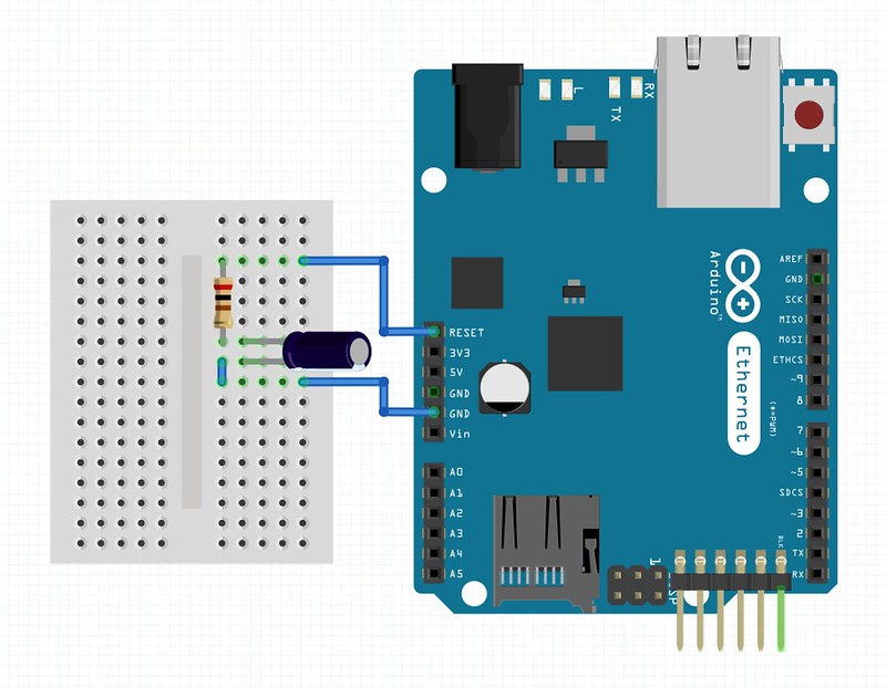
Test circuit layout
John's test code relies on the fact that if the W5100 is able to start properly then the call server.begin() will succeed, and the code will not hang in the setup() loop. A successful completion of the setup means that the main loop() will run and the LED at pin 2 will flash at 1Hz. I have reproduced the test code below with some small modifications.
1 2 3 4 5 6 7 8 9 10 11 12 13 14 15 16 17 18 19 20 21 22 23 24 25 26 27 | #include <SPI.h>
#include <Ethernet.h>
int LED_PIN = 2
byte mac[] = { 0xDE, 0xAD, 0xBE, 0xEF, 0xFE, 0xED };
IPAddress ip(192,168,100,21);
// Initialise the Ethernet server library
EthernetServer server(80);
void setup() {
// Initialise digital pin 2 as an output.
pinMode(LED_PIN, OUTPUT);
Ethernet.begin(mac, ip);
server.begin();
}
void loop() {
// Turn the LED on (HIGH is the voltage level)
digitalWrite(LED_PIN, HIGH);
// Wait for a second
delay(1000);
// Turn the LED off by making the voltage LOW
digitalWrite(LED_PIN, LOW);
// Wait for a second
delay(1000);
}
|
My findings have been a little different from John's, but interesting nevertheless. I have found that even if server.begin() does fail the LED will still blink, meaning of course that loop() is being executed.
The experiments below have the network adapter configured with the ip address 192.168.100.21. I also disconnected the pin 2 LED in an attempt to only measure the current draw of the DCcduino (and shields).
W5100 Without RC Network
This is just the DCcduino with the W5100 network shield attached.
Loop LED Behaviour
Flashed at 1Hz once out of setup().
Network Adapter Behaviour
Network adapter LEDs flicker in unison occasionally, frequency undetermined. The only light that stays on constantly is the PWR LED.
Command Line Ping
First 6 pings:
$ ping 192.168.100.21
PING 192.168.100.21 (192.168.100.21): 56 data bytes
Request timeout for icmp_seq 0
Request timeout for icmp_seq 1
Request timeout for icmp_seq 2
Request timeout for icmp_seq 3
ping: sendto: No route to host
Request timeout for icmp_seq 4
ping: sendto: Host is down
Request timeout for icmp_seq 5
ping: sendto: Host is down
Power Supply
9 volts via the 5.5mm DC input socket on the DCcduino; current usage on the bench supply oscillates between 170mA and 250mA with pin 2 LED disconnected.
W5100 With RC Network
This is the DCcduino, complete with the W5100 network shield and the prototype shield with an RC network built on it.
Loop LED Behaviour
Flashed at 1Hz once out of setup().
Network Adapter Behaviour
Network adapter LEDs steadily on (PWR, LNK, 100M, FULLD) and the TX RX LEDs light on ping response.
Command Line Ping
First 6 pings:
$ ping 192.168.100.21
PING 192.168.100.21 (192.168.100.21): 56 data bytes
64 bytes from 192.168.100.21: icmp_seq=0 ttl=128 time=7.868 ms
64 bytes from 192.168.100.21: icmp_seq=1 ttl=128 time=4.131 ms
64 bytes from 192.168.100.21: icmp_seq=2 ttl=128 time=1.891 ms
64 bytes from 192.168.100.21: icmp_seq=3 ttl=128 time=2.721 ms
64 bytes from 192.168.100.21: icmp_seq=4 ttl=128 time=0.809 ms
64 bytes from 192.168.100.21: icmp_seq=5 ttl=128 time=0.855 ms
Power Supply
9 volts via the 5.5mm DC input socket on the DCcduino; current usage on the bench supply steady at 190mA with pin 2 LED disconnected.
Only Time will Tell
I am hoping that finally, once again thanks to John for putting me on the right track, I have a viable solution to reliably leaving remotely network connected Arduinos to get on with their business. Early indications with the RC network fix are promising, however as the saying goes... only time will tell!
Comments
comments powered by Disqus