Contents
The Problem
How would one be able to restart a system that has been deployed in a remote area which gives no immediate access for human intervention? The answer is to give the system an ability to reset itself in case of a system crash.
This is where a watchdog timer (WDT) comes into use. It is a hardware based timer capable of automatically resetting a system should the main program fail to periodically send out a heartbeat. Now, the Arduino does indeed have a WDT on board, as do probably all microcontrollers, but a small amount of reading will inform you that once it has started running a sketch, there is no software function that has the same effect as pressing the reset button.
I'll admit that arranging for the possibility that you may want to have external WDT capability in your program is not a run of the mill requirement. This changes, however, when you start to introduce things like supporting external boards, such as Ethernet modules like the ENC28J60. There are some situations where a small power fluctuation can cause a module such as that to crash, and in that case a reset is the only option for recovery.
There are many examples where people have tried to address resetting the Arduino using just software and, for example, connecting one of the I/O pins to the reset pin to trigger the reset. However, ATMEL themselves, in their ATmega328 datasheet, describe the reset function as requiring a pulse width of at least 2.5µs, and that may not be possible with self shunting the Arduino. This is because as soon as the reset is activated, all the Arduino's I/O pins switch to input mode, meaning that making a long enough reset pulse is not guaranteed.
So, how about an external circuit as a solution? As it turns out, it was easier than I thought it would be. Read on...
An External Solution
One solution for this problem is to have an external circuit act as a watchdog with the capability of activating the Arduino's reset port when the conditions dictate. After a fair amount of reading on the subject it seems that most sensible suggestions are based around an Astable Oscillator implementation using the popular, and almost infinitely versatile 555 timer IC [1].
The Circuit
Below is a circuit diagram containing an Arduino Pro Mini, a 555 based astable oscillator, and a heartbeat LED indicator. This solution only really has to tie up one I/O pin on the Arduino which will function as the pulse output; the other I/O pin just lights up a pretty heartbeat LED - entirely dispensable if you are pushed for I/O real estate.
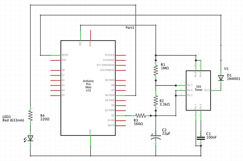
Arduino 555 Watchdog Timer Circuit Diagram
Read on for an outline on how the circuit works.
How it Works
Basically, I am using the above circuit as a countdown timer that restarts itself once it gets to zero, with an interrupting reset facility added in. So let's see what the circuit does:
When the circuit is powered up, pin 3 (Q) goes high and the capacitor C2, begins to charge, taking current from VCC on the Arduino via the resistors R1 and R2. Note that the values of resistors R1 and R2 dictate the time taken for C2 to charge.
If the voltage in the capacitor is ever allowed to reach 2/3 of the VCC voltage, the 555 pulls down pin 7 (DIS), in turn discharging C2 through R2 until it drops to 1/3 of VCC's voltage. Note that the value of R2 dictates how long it takes for C2 to discharge.
At this point the 555 stops discharging and the whole cycle begins again - this is the countdown timer having reached zero, and starting the countdown all over again.
Once the discharge of C2, is complete, the connection between pin 3 on the 555 and RESET on the Arduino is pulled low, thus resetting the Arduino through the diode D1.
In order to prevent the 555 from constantly charging and discharging it needs a periodical reset, and this is where pin D2 on the Arduino is used. During normal operation, pin D2 is held high, but in order to reinitialise the timer, pin D2 is made to go low, thus discharging C2 through the resistor R3. This, of course, interrupts the charge cycle of the 555 and takes it back to the start point.
So the trick to keep the Arduino from resetting and thus in a steady state is to make sure that the capacitor C2 never reaches 2/3 VCC voltage by dropping pin D2 in good time. The moment that pin D2 stops dropping, perhaps because of a crash in the software running on the Arduino, C2 reaches the critical 2/3 VCC voltage and the discharge process as described above begins.
Regarding Timing
Some notes regarding charge/discharge time for the watchdog circuit. I was looking for a timeout of somewhere between 10 and 20 seconds so my component values are thus reflected below.
C2 Charge Time
The formula for calculating charge time in the watchdog circuit, using standard astable 555 maths, is as follows:
So for the values of R1, R2 and C2 I have chosen, the maximum time the circuit will wait for a heartbeat, before resetting the Arduino, will be:
C2 Discharge Time
The formula for calculating discharge time in the watchdog circuit, again using standard astable 555 maths, is below:
With the values of R2 and C2, we have:
The above is the minimum time the Arduino will have spend with the pulse pin D2 pulled low in order to sink sufficient current from the capacitor C2 to ensure that it is at 1/3 charge.
Testing it Out
I decided to prototype the watchdog circuit on a breadboard using the Arduino Pro Mini 5v - a favourite of mine at the moment.
Breadboard layout
Below is the breadboard layout - nothing fancy apart from the heartbeat LED!
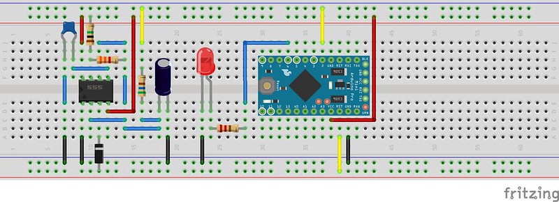
Arduino 555 Watchdog Timer Circuit Breadboard Assembly
A Test Program
The code below is fairly straightforward; just loop and count 10 seconds before issuing another heartbeat to the watchdog. This is just a basic script to test the functionality of the watchdog; there are myriad reasons you might enable a heartbeat to be sent, such as: a resource being available on a network, or a signal on one of the I/O pins. The choice of application is yours.
1 2 3 4 5 6 7 8 9 10 11 12 13 14 15 16 17 18 19 20 21 22 23 24 25 26 27 28 29 30 31 32 33 34 35 36 37 38 39 40 41 42 43 44 | int pulsePin = 2;
int led = 4;
unsigned long lastHeartbeat = 0;
unsigned long lastUptimeReport = 0;
void setup() {
Serial.begin(9600);
Serial.println("*** Arduino reset ***");
pinMode(led, OUTPUT);
// Send an initial heartbeat.
heartbeat(" <3 Initial heartbeat");
}
void loop() {
unsigned long uptime = millis();
// Every 10 seconds issue a heartbeat...
// ...unless you have a reason not to!
if ((uptime - lastUptimeReport) >= 10000) {
lastUptimeReport = (uptime - (uptime % 10000));
heartbeat(" <3 Still alive!");
}
// delay in between loops
delay(500);
}
/**
* Utility function to handle heartbeat pulse generation
* LED and a serial message
*/
void heartbeat(String message) {
// Sink current to drain charge from C2
pinMode(pulsePin, OUTPUT);
digitalWrite(pulsePin, LOW);
// LED on
digitalWrite(led, HIGH);
// Give enough time for C2 to discharge (should discharge in 50 ms)
delay(300);
// Return to high impedance
pinMode(pulsePin, INPUT);
// LED off
digitalWrite(led, LOW);
lastHeartbeat = millis();
Serial.println(message);
}
|
Test Plan
So the idea of the test was to see what happened when I simulated a failure of some sort by stopping the heartbeat pulse from the Arduino to the watchdog. I was hoping that once the watchdog lost the pulse, it would wait a maximum of about 15 seconds before resetting the Arduino. I would expect the watchdog to keep resetting the Arduino until it got a heartbeat response back. I would also expect that a simple reset of the Arduino, by pressing the on board reset button would not adversely affect things.
Thus the test plan was as follows:
- Start the Arduino
- See it run normally with no reset
- After 60 seconds, disconnect D2 (the pulse pin)
- See it reset every 15 seconds or so
- After 120 seconds, reconnect D2
- See it run normally with no reset
- After 180 seconds, press reset on the Arduino
- See it run normally with no reset
- End test
Below is an annotated extract of a test run from the serial console:
<< Start >>                              )--- (1)
    *** Arduino reset ***                |
     <3 Initial heartbeat                |
     <3 Still alive!                     |
     <3 Still alive!                     |
     <3 Still alive!                     |--- (2)
     <3 Still alive!                     |
     <3 Still alive!                     |
     <3 Still alive!                     |
<< Disconnected D2 after 60 secs >>      )--- (3)
     <3 Still alive!                     |
     <3 Still alive!                     |
     <3 Still�*** Arduino reset ***      |
     <3 Initial heartbeat                |
     <3 Still alive!                     |
    *** Arduino reset ***                |--- (4)
     <3 Initial heartbeat                |
     <3 Still alive!                     |
    *** Arduino reset ***                |
    <3 Initial heartbeat                 |
<< Reconnected D2 after 120 secs >>      )--- (5)
     <3 Still alive!                     |
     <3 Still alive!                     |
     <3 Still alive!                     |
     <3 Still alive!                     |--- (6)
     <3 Still alive!                     |
     <3 Still alive!                     |
<< Pressed reset after 180 secs >>       )--- (7)
    *** Arduino reset ***                |
     <3 Initial heartbeat                |
     <3 Still alive!                     |
     <3 Still alive!                     |--- (8)
     <3 Still alive!                     |
     <3 Still alive!                     |
     <3 Still alive!                     |
<< End >>                                )--- (9)
All in all, after a few days of fiddling about, testing and more fiddling about I felt that I reached a point where I was happy enough with the circuit to go ahead and make a prototype on veroboard.
The Final Build
The intention of this watchdog timer project was to get the circuit retrofitted to an already installed Arduino, so I had to allow for two sets of male breakaway header pins to be added. This would enable me to be present the watchdog as a daughter board to the installation.
Below is an image of the completed watchdog timer. Note that the use of header pins means that the business part of the circuit is off to one side. The grey and white flying lead is for the heartbeat LED.
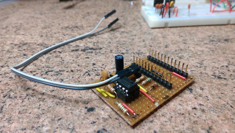
Watchdog Module for the Arduino Pro Mini
Luckily, I had already planned for the possibility of retrofitting a circuit to my Arduino Pro Mini, so I had soldered in some long tailed female header connectors. This meant that fitting the watchdog was a simple case of 'plug it in'.
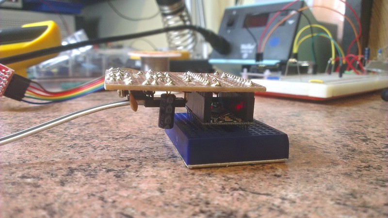
Watchdog Module Retrofitted to the Arduino Pro Mini
Above you can see the Arduino up and running with the watchdog circuit retrofitted.
In the Field
After a few weeks being plagued by crashes from a remote installation (my soil temperature measuring project, in case you are interested) using an Arduino with an ENC28J60 Ethernet module, I became fed up with the drag of having to recycle the power supply and the gaps in the data I was gathering. This drove me to researching watchdog circuits and hence the work in this article. I am happy to report that since the installation of the watchdog daughter board I have had some four months of uninterrupted work from the installation.
| [1] | Okay, so I love these ICs - I spent many an hour abusing these in my youth. |
Comments
comments powered by Disqus